Lab 4: Motor Drivers
Wiring the motor drivers
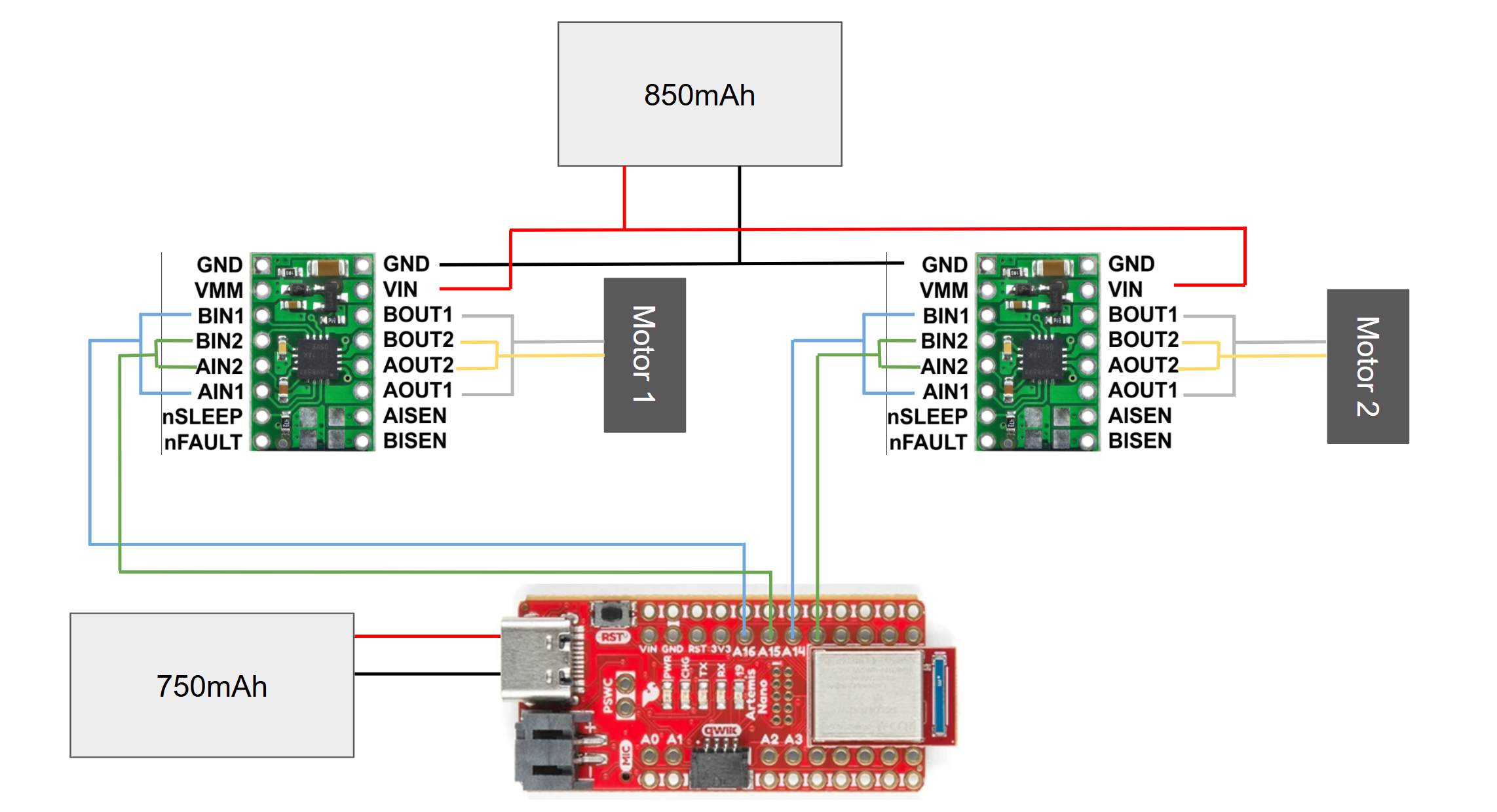
To send signals to my motor drivers, I decided to use pins 13, A14, A15, and A16 on the Artemis board. While their proximity can increase the risk of a short, their location allows for compact wiring. Additionally, each pin is able to send PWM signals, as indicated by the (~) symbol on the Artemis data sheet.
Wiring schematic
Using two separate batteries protects the Artemis from voltage spikes caused by the inductive load of the motors. Without this, powering off the motors while they are turning could damage the board or other sensors in the circuit.
Oscilloscope testing
Before mounting anything to my car, I tested the signal coming out of the driver with an oscilloscope. This allowed me to sanity check my wiring and get any debugging out of the way before making any changes permanent. To achieve this, I used a power supply set to 3.7V to simulate the 3.7V that the 850mAh battery will be providing to the driver. I then hooked up the output wires of the driver to a scope, allowing me to see the voltage that will be provided to the motors.
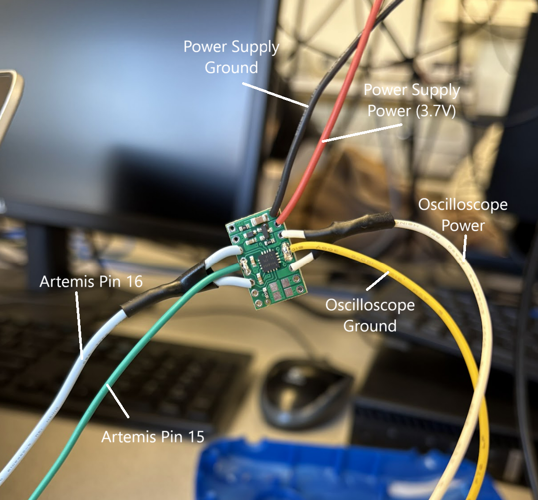
Motor driver and connections for testing
To send a PWM signal to my driver, I used a basic analogWrite() command from the Artemis:
#define AB1IN_LEFT 16
#define AB2IN_LEFT 15
void setup() {
    pinMode(AB1IN_LEFT,OUTPUT);
    pinMode(AB2IN_LEFT,OUTPUT);
}
void loop() {
    analogWrite(AB1IN_LEFT,100);
    analogWrite(AB2IN_LEFT,0);
}
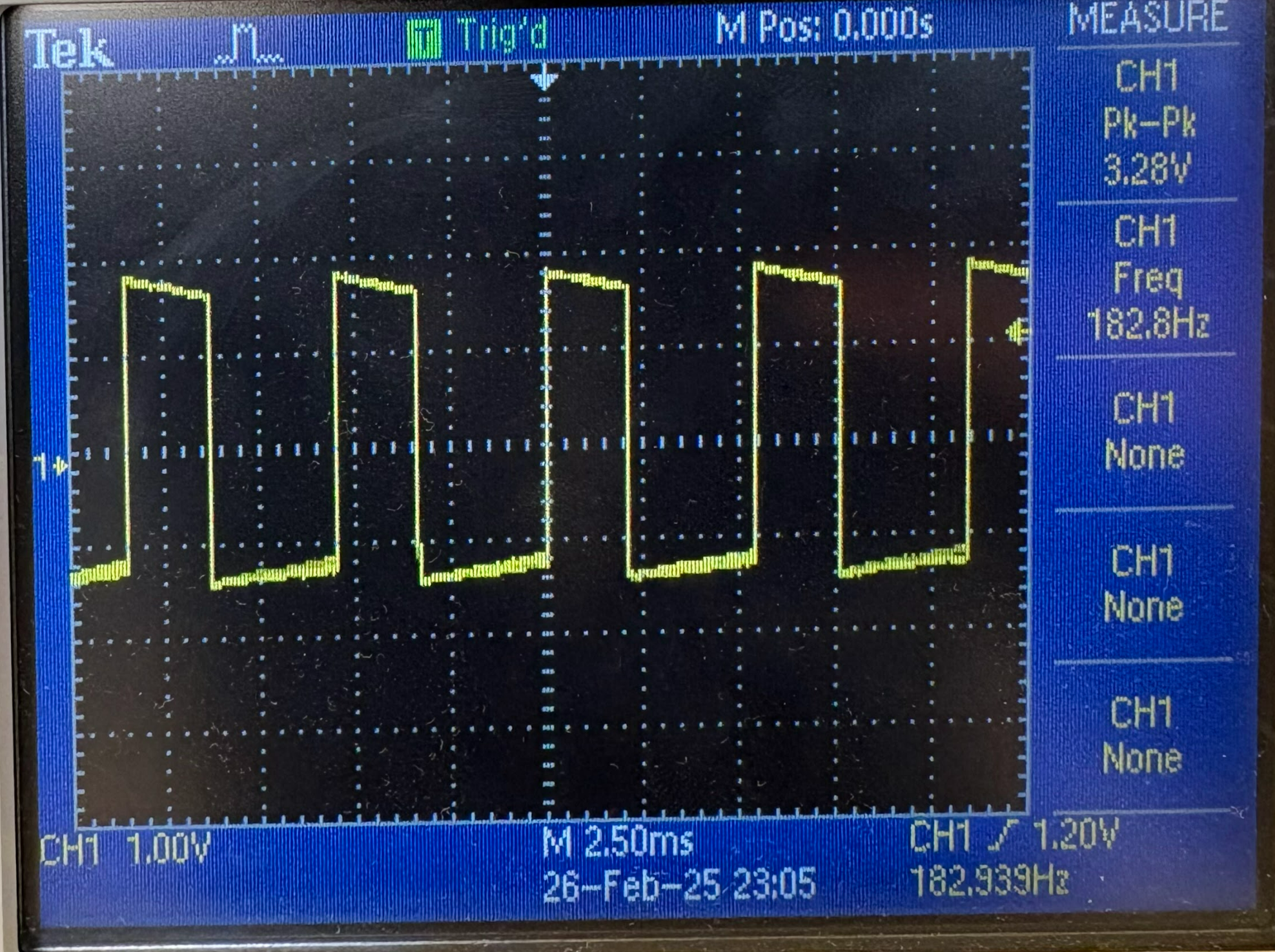
The result was a clear PWM signal that matches the ~40% (100/255) duty cycle that the Artemis was sending to the driver:
Scope result
Now that I had verified my driver performs as expected, I replaced the scope probes with the power and ground wires on my robot's motors. She spins!
Next, I replaced the power supply with my 850mAh battery. I also flashed new code that tested both directions of rotation.
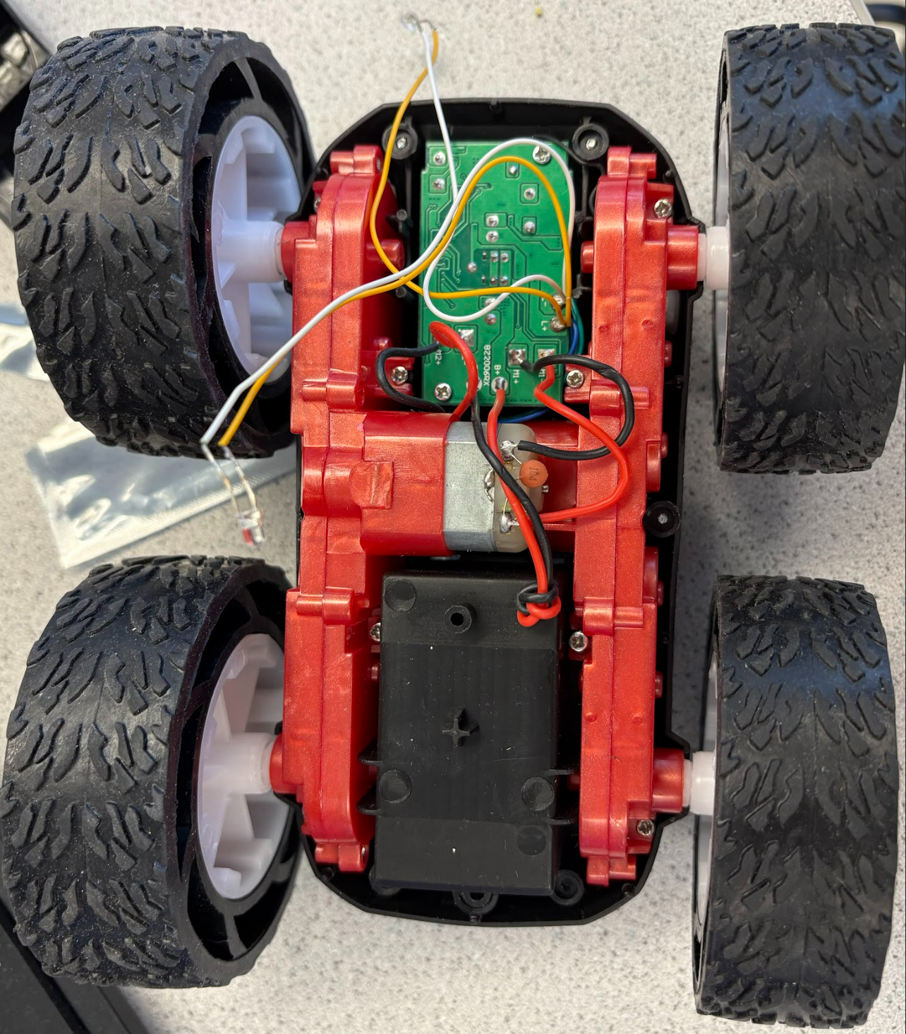
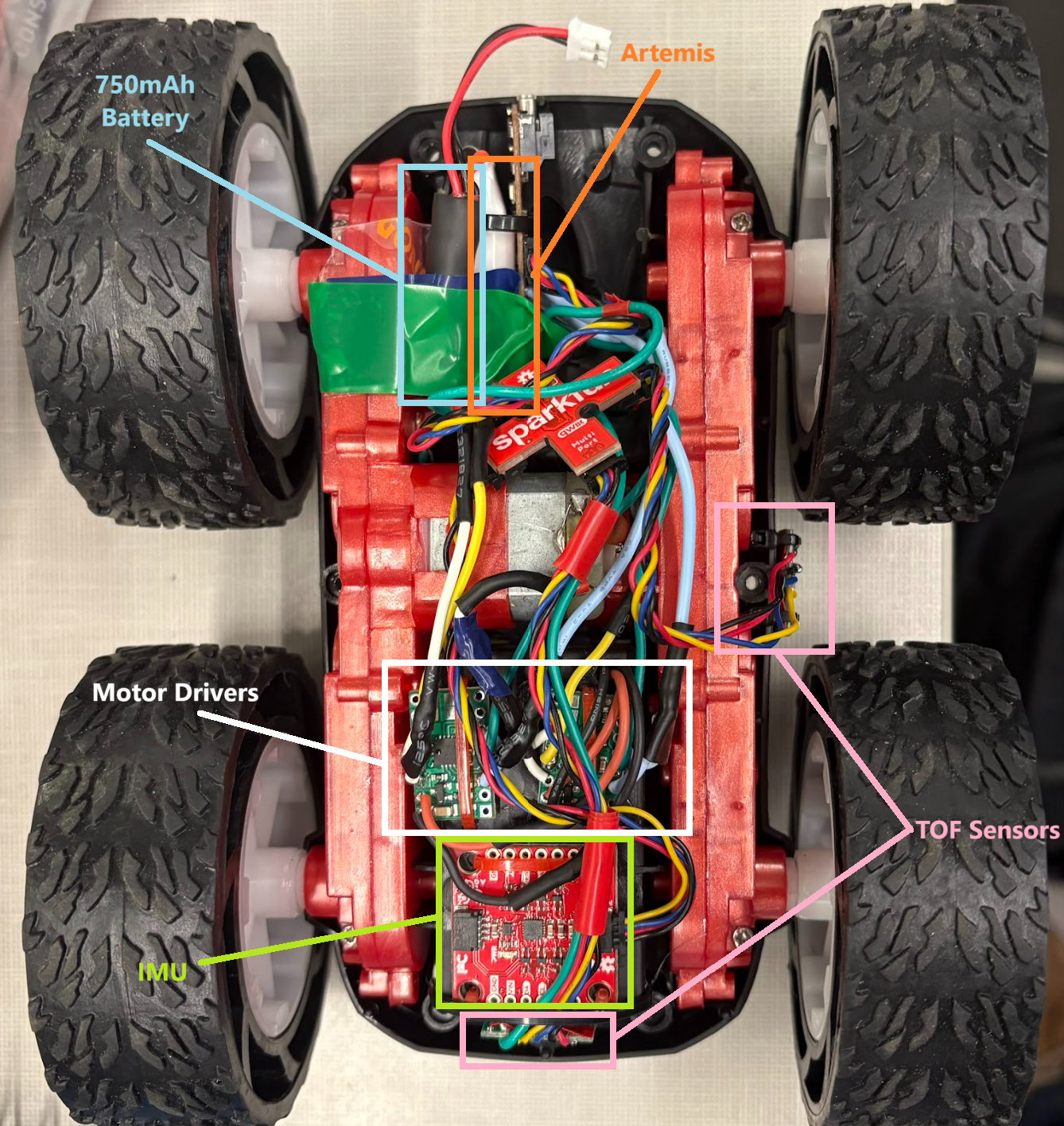
With all the components working as expected, I next mounted components on my car. I used zipties for this primarily, as they are a more rugged fastener than tape, yet are still easy to remove. I poked holes in the plastic housing and was also often able to mount using holes already present on the sensors.
Before (stock electronics)
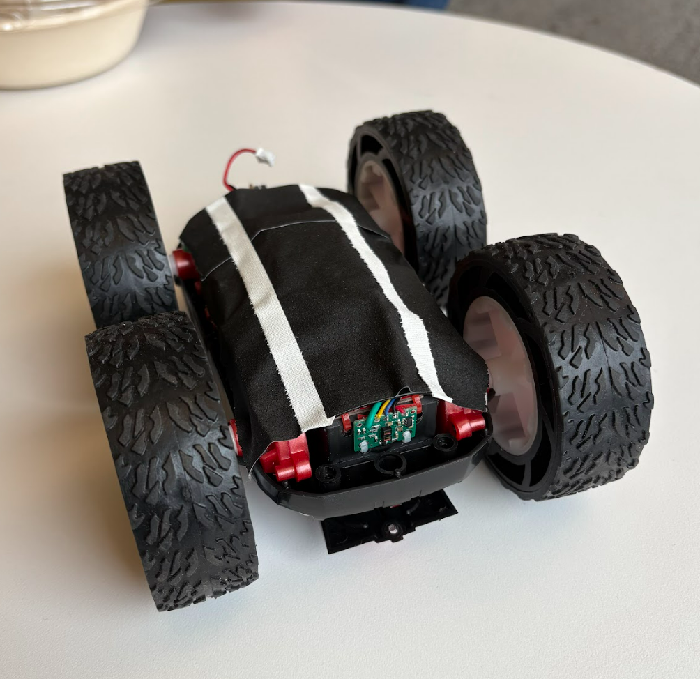
After!
After mounting the electronics, I took the robot for a test drive:
The car drives, but there is some drift due to imbalance between the motors. I implemented a calibration factor to throttle the stronger motor - this is a multiplicative factor rather than an additive constant, because the imbalance seemed to become worse at higher frequency PWM signals. I also chose a factor that reduced the stronger motor rather than increasing the weaker one, because I didn't want the weaker motor saturating at 255 before the other one. At this point, I also took the time to define pins and variables in ways that made sense for easy editing down the line.
#define FORWARD_RIGHT 16
#define BACKWARD_RIGHT 15
#define BACKWARD_LEFT 14
#define FORWARD_LEFT 13
float c = 0.6; // Calibration factor
int speed = 200;
int cspeed = speed * c; // Corrected speed
void loop() {

// go forward
analogWrite(FORWARD_RIGHT,cspeed);
analogWrite(FORWARD_LEFT,speed);
analogWrite(BACKWARD_RIGHT,0);
analogWrite(BACKWARD_LEFT,0);
delay(1300);

//stay still
analogWrite(FORWARD_RIGHT,0);
analogWrite(FORWARD_LEFT,0);
analogWrite(BACKWARD_RIGHT,0);
analogWrite(BACKWARD_LEFT,0);
delay(2000);

}
This calibration factor helped the car drive straight while the motors were active, but I faced another issue with alignment. After I sent a stop command, the fact that the motors were spinning freely at different speeds would cause a turn at the end of any motion. This meant the car would drive stright until the signal ended, at which point it would spin out a little at the end of the motion. I was able to find a sort of sweet spot for my calibration factor that maximized straight active driving while minimizing the speed differential that caused this fishtail, but it isn't perfect (works best at slow speeds). In the future, I am planning to implement a ramp down for the motors, reducing the speed differential at the end of a motion.
Calibrated straight line test
To test the minimum PWM value required to get the car to start moving, I incrementally lowered the duty cycle until the car couldn't get going. I found this PWM value to be around 30 (~12%) for my system. Although this value is when the robot truly stops moving, steady motion only occurs above around 50 (~12%). Note that these numbers decrease pretty quickly as the battery discharges.
Lastly, I implemented turning. Turning the wheels on each side in opposite directions causes a torque on the car; however, the two axels do not want to rotate around the same point, so the wheels must slide on the ground in order to execute a turn. For this reason, a higher PWM value is needed to initiate turning motion rather than linear motion. I found that the minimum PWM value required to start a turn was 125 (~50%). Additionally, I used the calibration factor here as well to account for the motor imbalance.
// Right Turn
analogWrite(FORWARD_RIGHT,0);
analogWrite(FORWARD_LEFT,speed);
analogWrite(BACKWARD_RIGHT,cspeed);
analogWrite(BACKWARD_LEFT,0);
delay(2000);
Turning and open loop control
Collaboration
I worked with Jack Long and Lucca Correia extensively. I also referenced Wenyi's website from last year for wiring help.