Lab 5: Linear PID Control
Code Structure
To execute a PID-controlled movement, I established communication between my laptop and my robot as follows:
Functions were created on the Artemis for controlling the motors and collecting sensor data, allowing them to be called as needed.
A BLE command initiates the PID-controlled motion, which runs for 5 seconds while sensor and PID data arrays are populated.
Additional BLE commands transfer the recorded data from the Artemis to my laptop for plotting and analysis.
Before implementing any controller logic, I made sure to get this data flow working. This allowed me to efficiently debug and tune my controller.
Range/Samping Time
I set my TOF sensor mode to long to ensure proper controller behavior when the robot was still far from the wall. I also lowered the timing budget on the sensors to try to get more speed out of them.
distanceSensor2.setDistanceModeLong();
distanceSensor2.setTimingBudgetInMs(35);
distanceSensor2.setIntermeasurementPeriod(40);
Proportional control
I began by implementing a simple proportional controller. While I was able to get this logic working, it had some key issues:
- The controller had significant under/overshoot depending on the proportional gain.
- The target could only be reached when the car was travelling relatively slow.
I was able to improve the end behavior by implementing some clamping logic - this code snippet pulls up low speed values to ensure the deadband of the motor does not keep the car from making small adjustments when it is near the target.
// Pull input up to upper floor if it is not too low, considering negative values
if (control_input > -pid_lower_floor && control_input < pid_lower_floor) {
    control_input = 0;
} else if (control_input >= pid_lower_floor && control_input < pid_upper_floor) {
    control_input = pid_upper_floor;
} else if (control_input <= -pid_lower_floor && control_input > -pid_upper_floor) {
    control_input = -pid_upper_floor;
}
The result:
Getting to this result took considerable tuning of both the proportional gain as well as the floor inputs that deal with the motor deadband. Improperly tuned parameters lead to overshoot or a car that doesn't move at all. The overshoot could be reduced by lowering the gain, but this would mean a slower rise time. I settled on a Kp of about 1 here.
PD control
In order to better deal with the overshoot, as well as to allow me to run my robot faster, I decided to implement derivative control. I achieved this by keeping track of the previous error and previous time so I could calculate how the error was changing with time.
static float prev_error = 0; // Store previous error
static unsigned long prev_time = millis(); // Store previous timestamp

unsigned long current_time = millis();
float dt = (current_time - prev_time) / 1000.0; // Convert to seconds

pid_d[pidCounter] = kd * (e - prev_error) / dt;
I also the following piece of logic to deal with the fact that my PD logic was running much faster than my sensor data was coming in. Basically, this prevents the derivative term from thinking there is zero error when the PD error is calculated without a new TOF datapoint.
if (pid_d[pidCounter] == 0){
    pid_d[pidCounter] = last_d;
}
else{
    last_d = pid_d[pidCounter];
}
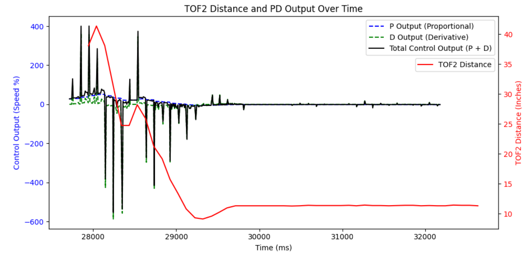
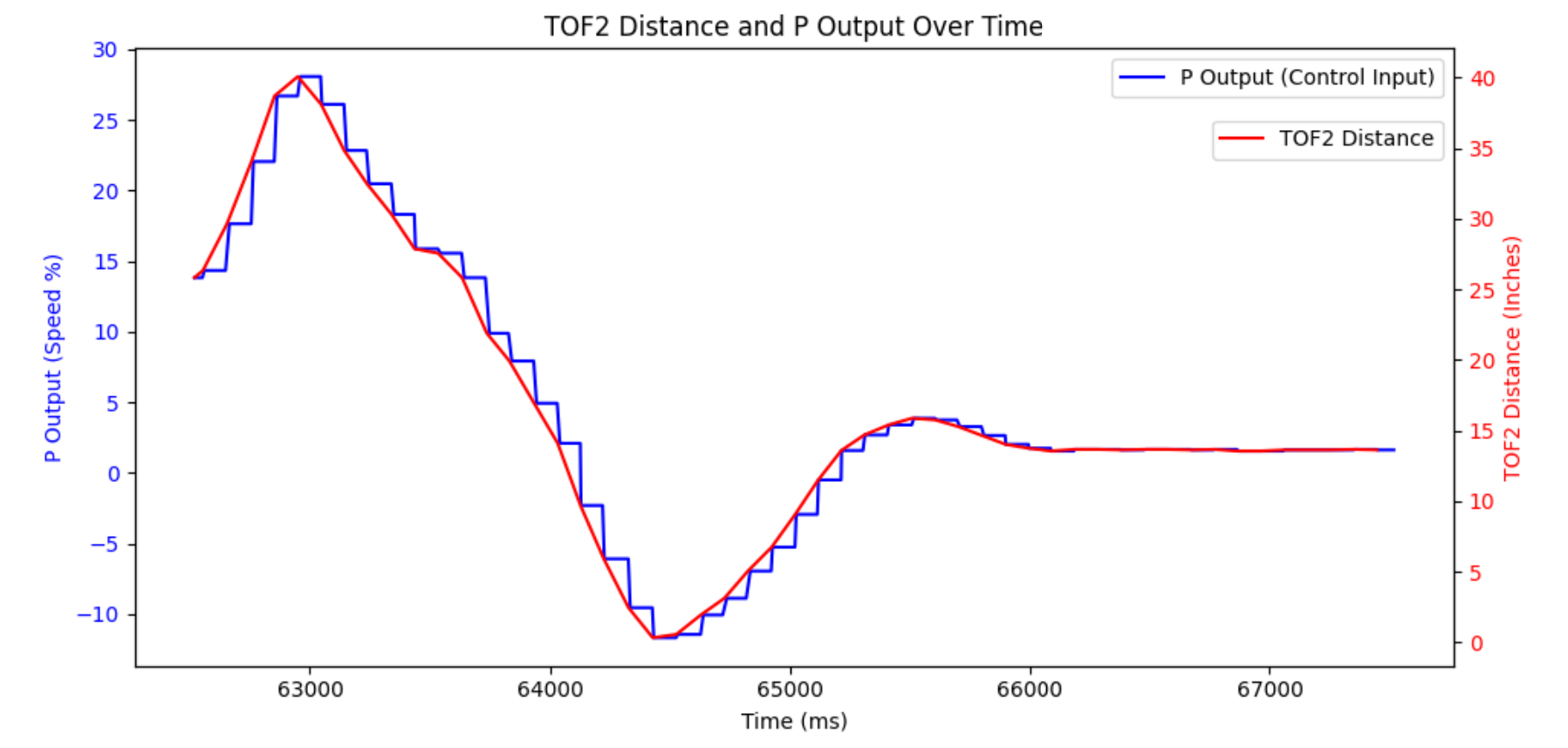
The results of this were very clear - the overshoot was now gone, and I was able to bump up Kp for a faster rise time. Any extra overshoot could be compensated for with a greater Kd.
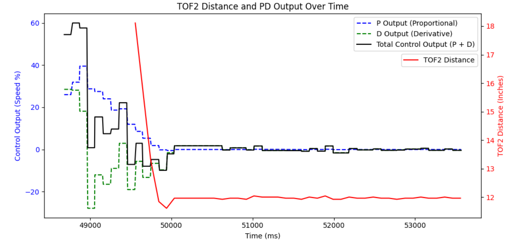
Kp of 2, Kd of 0.4
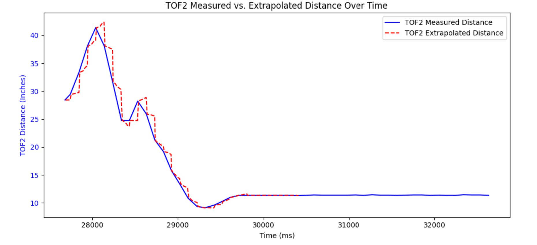
Extrapolation
To get even better performance, I want to do something about the TOF sampling rate. I have already written my controller logic to be independent of the sensors, so the data is coming in much slower than the PD logic is running. If I can estimate what the data points will be before I actually receive them, my system won't be as limited by this slow sensor speed. Here is the code I used to calculate the slope and extrapolated data:
if (new_data){

    current_distance =  tof2_array[tof2Counter - 1];
    tof2_extrapolated_array[pidCounter] = current_distance;
    new_data = 0;
    } else {
        // extrapolate next data point
        float dt = millis() - pid_time_stamps[pidCounter - 1];
        float speed = ( tof2_array[tof2Counter - 1] - tof2_array[tof2Counter - 2] ) / (tof2_time_stamps[tof2Counter - 1] - tof2_time_stamps[tof2Counter - 2] ); //slope
        current_distance = tof2_extrapolated_array[pidCounter - 1] + speed*dt;
        tof2_extrapolated_array[pidCounter] = current_distance;
    }
Honestly, my results didn't exactly improve. Looking at the extrapolated data, it looks choppy when compared to the original data. This causes some oscillatory/inconsistent motion in my robot. There is likely an issue in my code, but I haven't been able to find it. The derivative control is spiking wildly, but I've spent lots of time debugging and I haven't figured it out yet.