Lab 6: Orientation PID Control
Code Structure
Similarily to the last lab, I began by structuring the information flow of the system to enable quick debugging and tuning:
Functions were created on the Artemis for controlling the motors and collecting sensor data, allowing them to be called as needed.
A BLE command initiates the PID-controlled motion, which runs for 10 seconds while sensor and PID data arrays are populated.
Additional BLE commands transfer the recorded data from the Artemis to my laptop for plotting and analysis.
I made sure to define variables that change often as global variables in my artemis code. This way, I could define them in python before sending them over BLE, allowing me to change their values without reuploading to the artemis.
ble.send_command(CMD.START_YPID, f"{kp}|{ki}|{kd}|{target_angle}|{df_alpha}|{turn_floor}")
Sensor data
Given the drift correction and high sampling rate of the DMP built into the IMU, I decided to run my controller on this data. I followed Stephan Wagner's tutorial, and refactored his example code in a way that fit my BLE code structure. I defined a function that would get new yaw data and save it in a global array, and called this continually from my PID logic loop. This sensor runs faster than 1kHz, and can handle angular speed above 2000 degrees per second - this is way more than anything I expect to need for my controller.
Sending turn commands
My turn function takes a control input and uses it to execute a turn. It uses a calibration factor to account for the slightly mismatched motors.
Something that I improved on from last lab was the way I mapped the control signal to a speed. Rather than mapping my control value to be in the range 0-255 and then pulling up any low values to a floor, I just mapped my control input straight to the range of values above my motor deadband. This means that my proportional input is now more nuanced than just an on/off input.
turn(int speed)
{
// Speed input is a percentage out of 100%. Positive numbers go right, negative go left. 0 stops the car.
speed = constrain(speed, -100, 100);


if (speed > 0)
    {
    // turn right
    speed = map(speed, 0, 100, turn_floor, 255); //map percentage to pwm range (floor-255)
    int cspeed = speed * tc;
    analogWrite(FORWARD_RIGHT,0);
    analogWrite(FORWARD_LEFT,speed);
    analogWrite(BACKWARD_RIGHT,cspeed);
    analogWrite(BACKWARD_LEFT,0);
    }

if (speed < 0)
    {
    // turn left
    speed = -1 * speed;
    speed = map(speed, 0, 100, turn_floor, 255);

    etc...
To clarify, the result of this is that my control input is a percentage, where 1% corresponds to the lowest value that will still spin the car, and 100% is the highest speed the car can spin.
Proportional Control
With the infrastructure established, I started with a P controller. The DMP yaw data is already within range [-180, 180], so I just had to normalize my error to ensure I was turning in the direction closer to the target:
float error = current_yaw - target;
    while (error > 180) error -= 360;
    while (error < -180) error += 360;
Then, calculating the proportional term was a simple product:
ypid_p[ypidCounter] = kp * e;
The result was a controller that worked, but there were some issues.
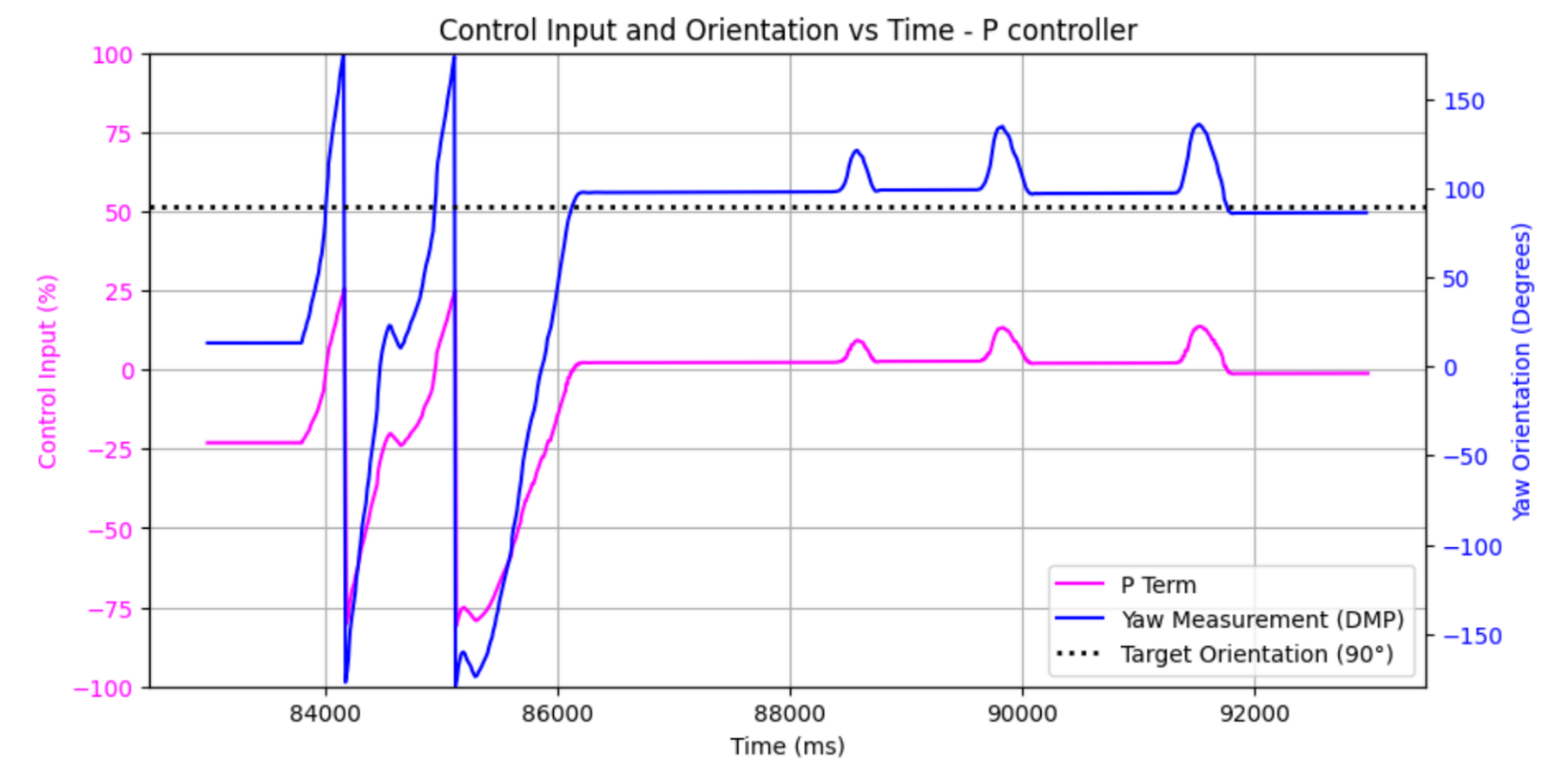
For one, the overshoot was massive - enough to send the robot in a full circle sometimes. Decreasing Kp kind of helped, but decreasing it too much meant the robot wouldn't move at all. Also, the steady state error got worse with a smaller Kp. This specific result was tuned to Kp = 0.3, and both problems are visible here. Something odd was that the behavior seemed better when responding to disturbance (in the latter half of this graph, for example) - more on that later.
Proportional-Derivative Control
At this point, I decided to add a derivative term to my controller to help manage the comical overshoot. I also added a low pass filter to this term to help deal with the large amount of noise I saw when I first implemented it.
unsigned long current_time = millis();
float dt = (current_time - yprev_time) / 1000.0; // Convert to seconds
if (dt <= 0) {
    dt = 0.001; // Prevent division by zero
}

float d_raw = kd * (e - yprev_error) / dt;  // Compute raw derivative

yfiltered_d = (1 - df_alpha) * yfiltered_d + (df_alpha) * d_raw;  // Apply low-pass filter
ypid_d[ypidCounter] = d_raw;  // Log raw derivative
ypid_df[ypidCounter] = yfiltered_d;  // log filtered derivative
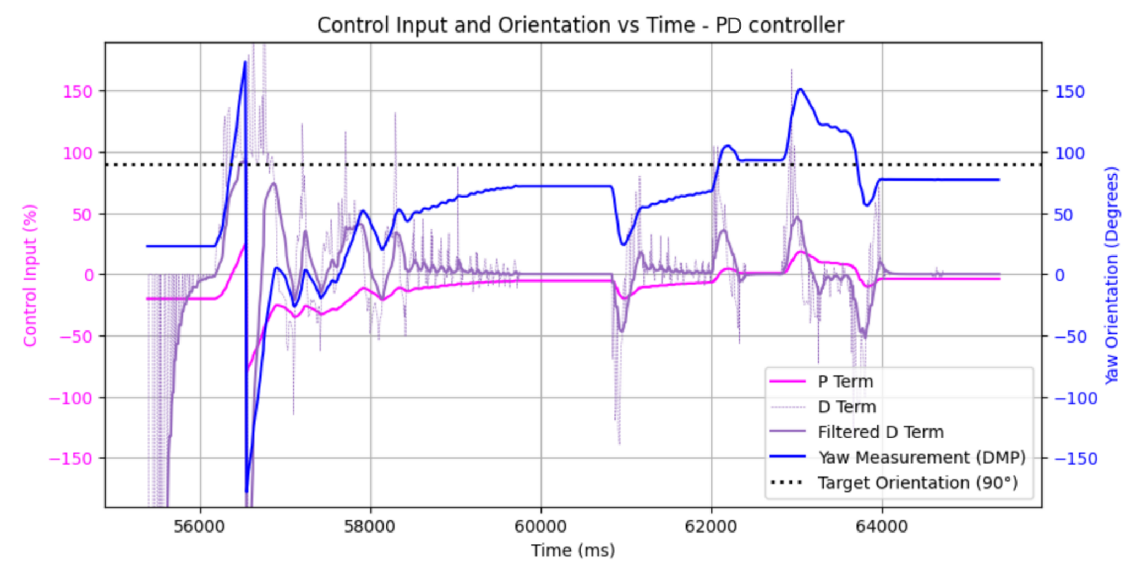
Kp = 3, Kd = 3
Honestly, this didn't really fix my overshoot issues. No matter how high I cranked up Kd, my car was still overshooting. I spent so many hours trying to tune this in different ways to fix the issue - I tried lowering Kp, lowering my motor input floor, adjusting Kd, adjusting alpha for the derivative lpf - nothing seemed to be working. All of my debugging showed expected values of my terms.
Finally, I starting paying more attention to the fact that this overshoot only happened on the first turn. I realised that in response to a disturbance, the controller worked fine. I had many theories about why this was happening, but I finally tried something that worked: holding a sustained motor input before executing the first turn. I'm not totally sure what's happening here, but it's clear that the motor is unpredictable and less responsive in the moments after it first receives current. The solution is literally as simple as manually overriding the controller in order to send a small speed value for the first two seconds:
if (time_passed < 2000){

    ycontrol_input = 1; // 1% input won't cause any turning
}
And the result is a remarkably improved response. Even with just a P controller, after this fix I was able to get great results. I cranked Kp up for faster response and less steady state error.
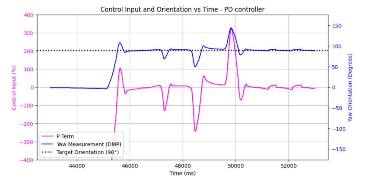
Kp = 6. You can hear the 'rev up' the motors do before starting active control.
After this realization I added my derivative term back. I adjusted alpha to make the term very noise resistant, and I was able to tune Kd to reduce the overshoot further while maintaining the quick response. I also added an error tolerance that would allow the car to stop the motors when it was close to its target; this reduced rapid oscillations near the setpoint.
if ( abs(e) < 3 ) {
    ycontrol_input = 0;
    turn(ycontrol_input);
} else {
    turn(ycontrol_input);
}
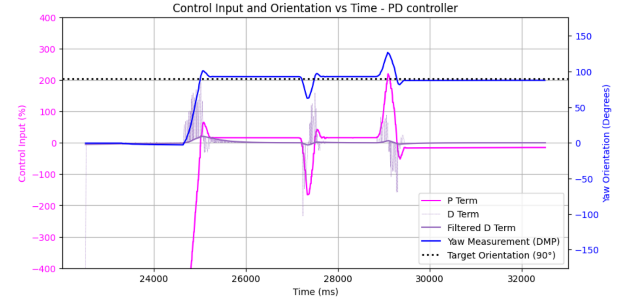
Kp = 6, Kd = 0.25, alpha = 0.01. Overshoot decreased even further!
At this point I am pretty happy with my controller. I don't see a need to add an integral term, as my high Kp term already leads to a small steady state error. Overshoot would normally be a concern with a high Kp, but since the car can change direction rapidly, it remains negligible and self-correcting (derivative term also helps reduce overshoot). Derivative kick is also not a huge issue for me, as the lpf on the derivative term keeps it from affecting the system too much. My biggest worry moving forward would be if I need to initiate a turn in a situation where I can't sit still and 'charge up' the motors for two seconds. This is something I will investigate in the future.
Collaboration
I worked with Jack Long and Lucca Correia extensively. I also referenced Stephan Wagner's tutorial for DMP data collection. Lastly, ChatGPT helped me make pretty plots.